Accelerator Controls & Beam Diagnostics Division
Booster Current Pulse Profile Measurement System

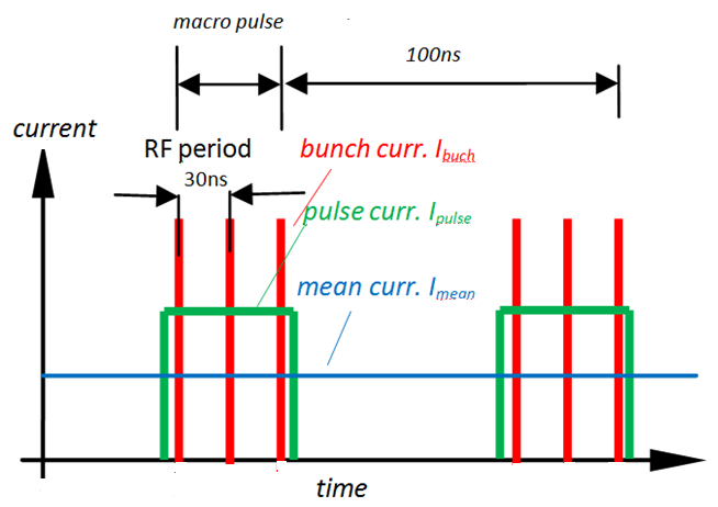
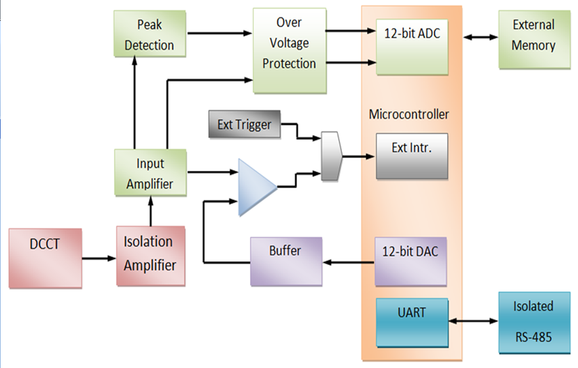
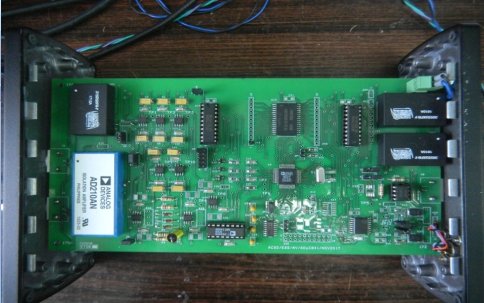
There is a common beam injector for both Indus-1 and Indus-2, consisting of a 20 MeV Microtron and a 450/550 MeV Booster Synchrotron. Microtron works as a pre-injector for the booster synchrotron, where electrons are generated and accelerated up to 20 MeV and delivers the beam at the repetition rate of 1 Hz. In the Booster Synchrotron, energy of the electron beam is raised from 20 to 450 MeV for injection into Indus-1 storage ring and up to 550 MeV for injection into Indus-2 ring. A typical beam structure is shown in figure 1. A data acquisition system is developed which acquires the beam current information at 2.5 kSPS with 12-bit resolution. It stores the average booster beam current for every cycle of beam delivered from microtron and gets accelerated before its exit for injection in Indus-1 and Indus-2. This system is synchronized with the master trigger and continuously monitors each injection cycle. Block diagram and hardware is shown in figure 2 & 3 respectively. This system is aimed to facilitate study of variation in the average beam current profile, over several cycles during injection in Indus-1 and Indus-2.

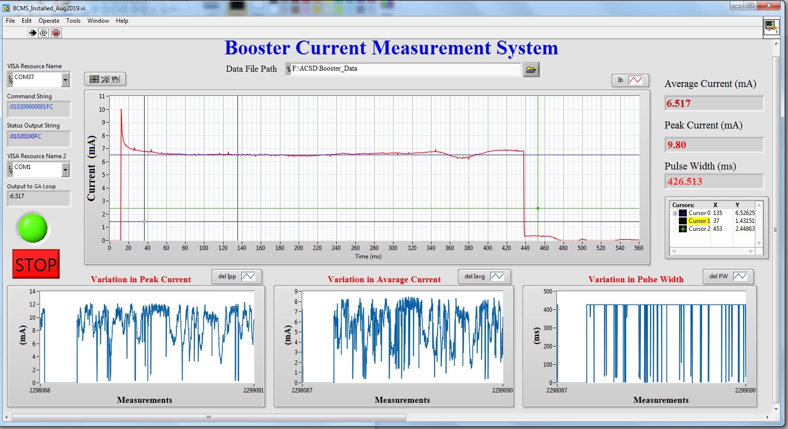
LabVIEW based graphical user interface (GUI) is developed (figure 4) which shows the complete profile of average beam current as it enters in to booster synchrotron and gets accelerated during multiple circulation in the ring and finally its exit from the ring. Variation in average current, peak current and duration is displayed online.

 
Structure of Electron Beam in Booster Synchrotron Block diagram of Data-acquisition System
Figure1: Structure of Electron Beam in Booster Synchrotron[Full Size Image] Figure2: Block diagram of Data-acquisition System[Full Size Image]
 
Data-acquisition System GUI of Beam Current Measurement System
Figure3: Data-acquisition System[Full Size Image] Figure4: GUI of Beam Current Measurement System[Full Size Image]
Best viewed in 1024x768 resolution