Accelerator Controls & Beam Diagnostics Division
Programmable Control Module for Linac Scanning Magnet Power Supply

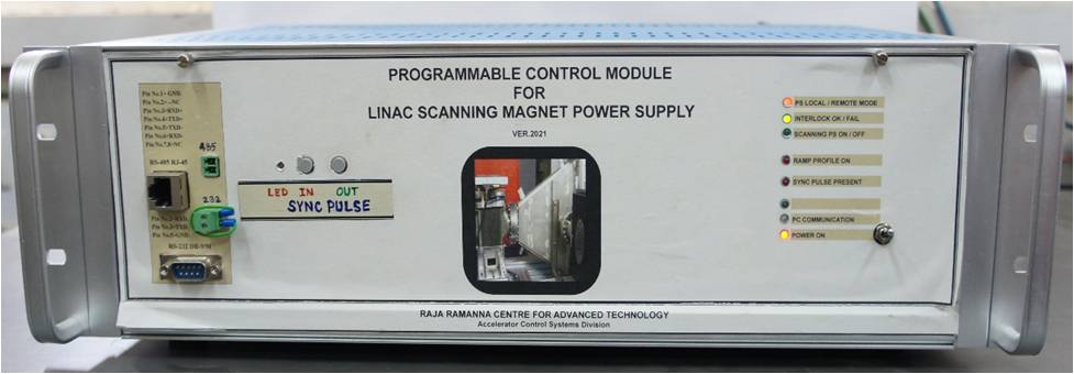
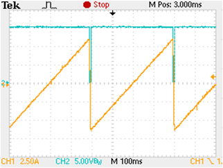
A time varying magnetic field is required for vertically scanning the electron beam. This magnetic field is produced with the help of scanning magnet and associated power supply to irradiate the product holding box from bottom to top. For this power supply, a bipolar ramp reference profile is generated through Programmable Control Module (PCM) to achieve uniform dose distribution inside the product under irradiation. The ramp profile can be adjusted in amplitude and time scale. The PCM which controls and provides the ramp reference for Scanning Magnet Power Supply (MPS), comprises hardware of in house developed FPGA board (Xilinx Spartan 3), analog-digital I/O board and a controller board. The PCM measures the positive and negative current peak values of power supply for confirming the correctness of the followed ramp profile. The PCM also measures the ramp up and retrace time of power supply current profile.

Main Features:

  • Analog ramp reference generation for scanning magnet power supply with 0.05% accuracy
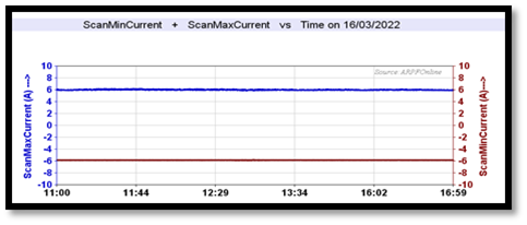
  • Reading the positive and negative peak current of power supply read back with 0.05% accuracy
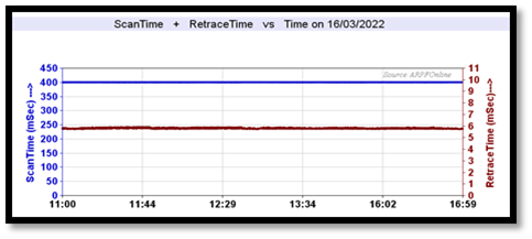
  • Scan time measurement with 0.01% accuracy (ramp time and retrace time)
  • 8 digital control signals and 8 status read back signals for remote operation of P/S.
  • Programmable ramp up time from 100 mS to 1 sec, retrace time from 3 mS to 10 mS.
  • four segment ramp reference with individual time and amplitude settings
  • Adjustable offset setting (base setting)

Figure1: Snapshot of PCM for SMPS Figure2: Snapshot of reference generated by PCM
Figure1: Snapshot of PCM for SMPS[Full Size Image] Figure2: Figure: Snapshot of reference generated by PCM[Full Size Image]
 
Figure3: Snapshot of retrieved peak current data Figure4: Snapshot of retrieved scan time data
Figure3: Snapshot of retrieved peak current data[Full Size Image] Figure4: Snapshot of retrieved scan time data[Full Size Image]
 
Programmable Trigger Generator Module for Linac

A timing system for precisely time synchronized operation of Linac subsystems, measurements, irradiation process verification and process interrupt handling of various parameters and faults is required. Various delays are to be precisely adjusted to match with sub-system characteristics with respect to the master reference trigger. A 16 channel programmable trigger generator module is developed to accomplish all the requirements.

Main Features:

  • Pulse Repetition Rate (PRR) setting range: 1 Hz – 500 Hz
  • Adjustable delay range with respect to master trigger pulse: 2 µS – 2000 µS
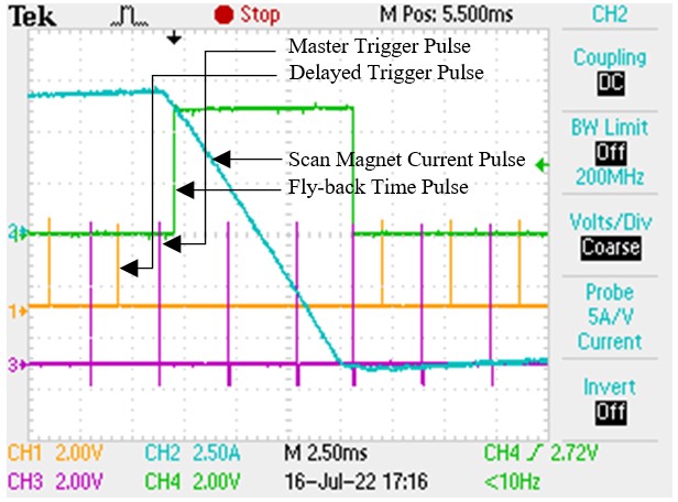
  • Provision to synchronize trigger output with external pulse input e.g. Scanning P/S pulse
  • PRR limit set facility as per user requirement with authentication
  • Selectable mode Free running / Count mode. Count mode range: 00001 – 30000 count pulses
  • Selectable: Operation mode / Diagnostic mode, Diagnostic mode facilitates beam parameters measurement to verify the Linac system.

Figure5: Snapshot of Programmable Trigger Generator for Linac Figure6: Snapshot of Trigger pulses with synchronization
Figure5: Snapshot of Programmable Trigger Generator for Linac[Full Size Image] Figure6: Snapshot of Trigger pulses with synchronization[Full Size Image]
 
Best viewed in 1024x768 resolution