| Accelerator Controls & Beam Diagnostics Division |
| FPGA with Controller Based ECM |
|
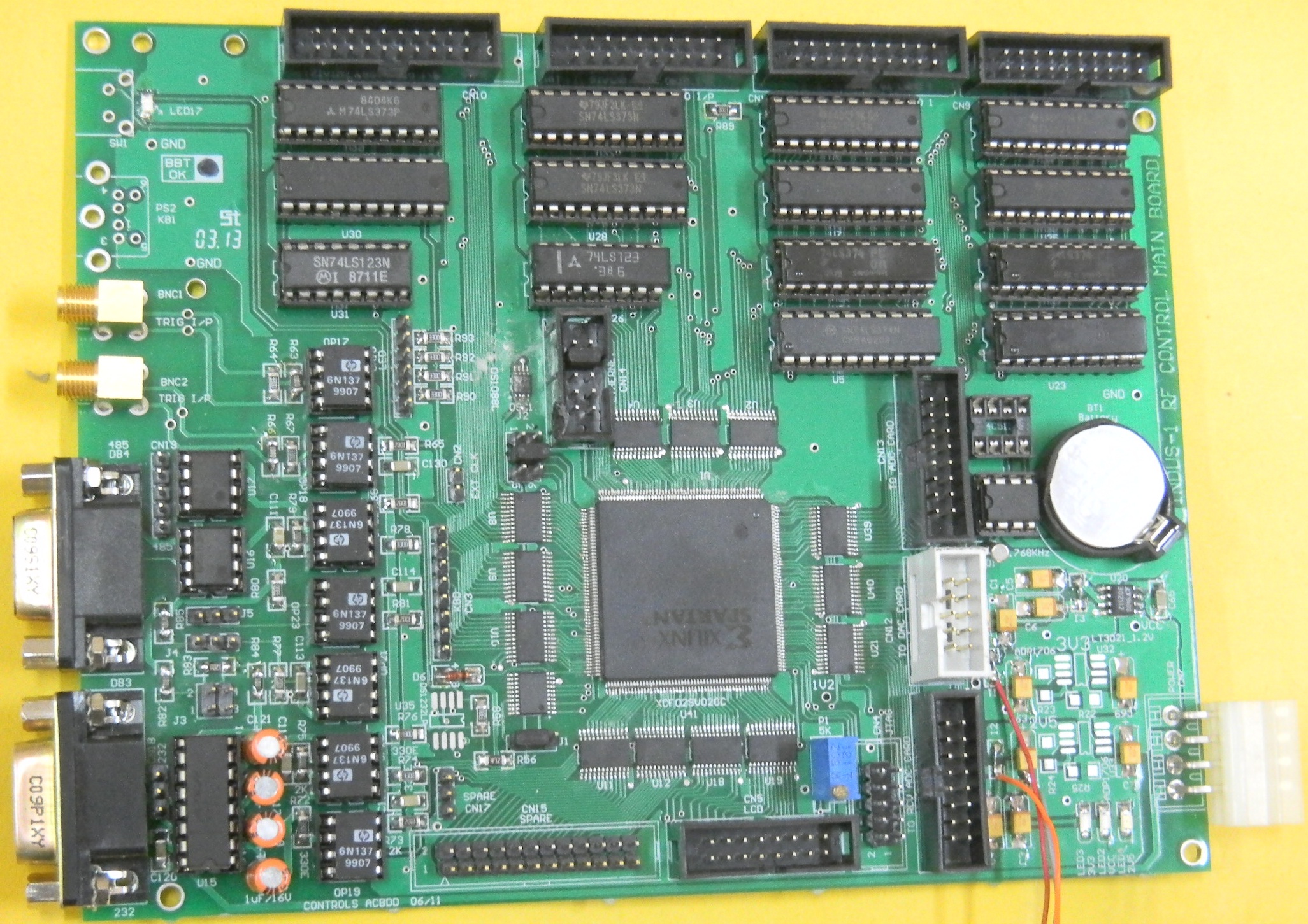
The core of the system is an FPGA (Xilinx Spartan 3 series) based modular hardware box called Equipment Control Module (ECM).
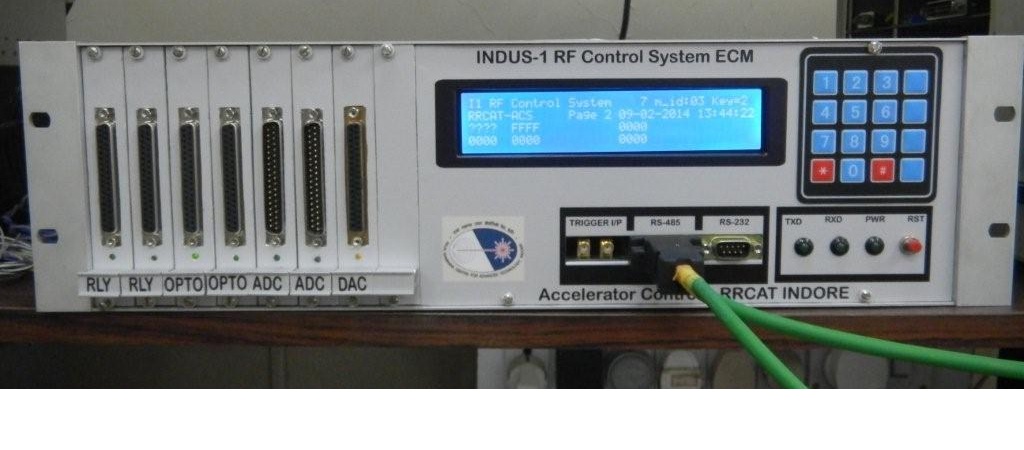
The multiple ECMs are used to cater to the signal requirements of distributed RF subsystems. The ECM provides local LCD display, LED indicators, 4x4 key pad, communication ports and trigger inputs. It has 32 control signals, 32 status signals, 32 analog inputs and 4 analog outputs to interface with the subsystem.
Main features:
- Data acquisition update rate of ~ 10 Hz.
- Local operation from ECM front panel.
- Local data monitoring on LCD display.
- Ramp generation feature with fine setting of gap voltage at injection & final energy level.
- Smooth switching from DC to Ramp and vice versa.
- Programmable slope for smooth analog signal settings.
- System last state restore feature on power up.
- 16 bit ADC & 5KSPS for all 16 channels.
- Ext. trigger input for event based sampling.
- Time stamping using Real Time Clock (RTC).
|
 |
 |
| Figure1: FPGA with Controller Based ECM [Full Size Image] |
Figure2: Indus-1 RF System ECM [Full Size Image] |
| |
|


