|
Indus-1 Beamlines
|
|
AIPES Beamline
|
Introduction |
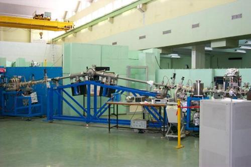
Angle integrated photoelectron spectroscopy beamline is designed to utilize photons in the energy range from 10 to 200 eV. The beamline operates at a vacuum better than of 10-9 Torr. The basic requirements for carrying out photoemission experiments are good photon flux and moderate resolution. Since toroidal grating monochromators (TGM) fulfil these two requirements, the present beamline is developed around it. The optical layout of the beamline is shown in Figure. Optical components of the beamline consist of a pre-mirror to focus the incident radiation, a monochromator to select the desired wavelength (energy) and a post-mirror to focus the monochromatic beam on the sample. In order to have good reflectivity in this energy range, a grazing incidence-reflecting optics is used. A toroidal pre-mirror which is kept at a distance 4000 mm from the source accepts radiation over horizontal and vertical acceptance angles of 10 and 2.5 mrad respectively. The grazing angle of incidence at the mirror is about 4.5°, giving a deviation of 9° after reflection. The reflected beam is brought to a focus at a distance of 2000 mm where the entrance slit of TGM is located. The pre-mirror section is followed by a TGM (Jobin Yvon-TGM2634) which contains three interchangeable gratings to cover a photon energy range from 10 to 200 eV. Monochromatized beam passing an exit slit falls on post-focusing toroidal mirror. Pt-coated post mirror refocuses the monochromatic beam from exit slit to a sample located at 990 mm in a PES spectrometer with magnification 1 : 1
|
|

| Source |
Bending magnet |
| Acceptance |
10 mrad (H) x 2.5 mrad (V) |
| Pre Mirror |
Pt-coated toroidal mirror demagnification 2 : 1 |
| Monochromator |
Toroidal grating monochromator (TGM-2600) |
| Energy range |
|
| Gratings (lines/mm) |
Energy range (eV) |
Resolving power (E/dE) |
| 200 |
10-23 |
650 at He(I) line |
| 600 |
23-69 |
950 at He(II) line |
| 1800 |
69-200 |
- |
| Post Mirror |
Pt-coated toroidal mirror |
| Spot size |
Typically 1 mm (H) x 1 mm (V) |
| Experimental station |
UHV compatible angle integrated photoelectron spectrometer |
|
Photo
 UGC-DAE-CSR PES Beamline
|
|
Research Activities
|
 Possible Origin of Electronic Phase Separation in La0.7Ca0.3MnO3
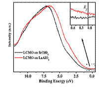
The effect of substrate strain on the electronic valence band structure of La0.7Ca0.3MnO3 (LCMO) thin films has been investigated. For this purpose La0.7Ca0.3MnO3 thin films have been simultaneously grown on SrTiO3 (STO) and LaAlO3 (LAO) substrates using pulsed laser deposition technique. The chemical characterization of these samples was carried out by core level x-ray photoelectron spectroscopy, and the structural characterizations by x-ray diffraction. Our experiments confirmed that all these samples have same chemical composition but different strain configuration. The electronic structure of these samples is probed through valence band spectroscopy measurements on Indus-1 synchrotron x-ray source. We observe that strain has large effect on the valence band of La0.7Ca0.3MnO3. The results are explained on the basis of change in the crystal field splitting due to Mn-O bond length The lattice parameters for powder sample of La0.7Ca0.3MnO3 (Pbnm space group) are a = 5.451, b = 5.4668 and c = 7.70 Å, where as the lattice parameters of SrTiO3 and LaAlO3 are 3.90 and 3.78 Å respectively. Therefore, it is natural to expect that the c-axis oriented LCMO will grow on the a-b plane along the diagonal of substrate unit cell and will occupy four such unit cells. Thus the film grown on STO and LAO substrates will have in plane expansive strain and compressive strain respectively. In the case of perovskite manganites six oxygen atoms surround the Mn atom in an octahedral cage, thus film on the STO substrate will have longer in plane Mn-O bond length than that of the film on LAO substrate. Thus the potential experienced by Mn ion due to neighboring four in plane oxygen anions will be more in the case of LAO substrate than that of the STO substrate. Therefore, there will be more crystal field splitting of Mn-3d i.e. Δ(t2g-eg) in LCMO on LAO substrate than that on the STO substrate. Table 1 summarizes the crystal field parameters obtain from the VBS. It appears that the binding energy associated with eg (itinerant) electron and the difference Δ(t2g-eg) critically depend on the strain condition. The present experimental studies reveal that the strain has large effect on the valence band structure. Therefore, the co-occurrence of different types of strain in a system will lead to the electronic phase separation as suggested by Ahn et al (K. H. Ahn, T. Lookman, and A. R. Bishop J. Appl. Phys. 99, 08A703 (2006).
|
|
Photo electron spectrometer
|

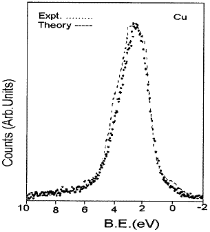
Valence band spectrum of Cu along with theoretical density of states (dashed line).
|
The experimental station of this beamline is an angle integrated photoelectron spectrometer, which was also designed and fabricated indigenously. It consists of (i) an energy analyzer, (ii) an experimental chamber with in situ heating and cooling arrangement, (iii) preparation chamber equipped with magnetic sample transfer rod, ion gun and diamond file scrapper, and (iv) the associated electronics with data acquisition system. The energy analyser consists of an electrostatic lens, a hemispherical analyser and a detector. The lens is a three-piece cylindrical system. Each cylinder is machined out of stainless steel and mirror-polished and coated with gold for good transmission of beam. The inner and outer hemispheres of the analyser are machined out of aluminum to an accuracy better than ±0.001 mm. The surfaces are then polished and coated with gold. The hemispheres are mounted on a fringe plate which is also machined out of aluminum. It has an entrance and an exit slit whose width can be varied from 1 mm to 3 mm in steps of 1 mm. The entire analyser assembly is mounted such that the inner hemisphere, the outer hemisphere and the fringe plate are isolated from each other by using teflon washers and bushes. There are six concentric rings made out of stainless steel mounted on fringe plate to correct the fringe field and improve the resolution of the analyser. These rings are positioned equidistantly in the gap between the two hemispheres. The inner and outer hemispheres have a radii of 65 mm and 125 mm respectively. A channel electron multiplier is used as a detector which is mounted at the end of the exit slit of the analyser.
|
|


